Basic function generators
If you have electronics as a hobby it’s unlikely you are going to get away without using a function generator. Its role is to make electrical waveforms over a range of frequencies while allowing to control the amplitude of the waveform. Some basic use cases include testing speakers or amplifiers, calculating inductance for coils or experimenting with resonant circuits such as for wireless energy transfer, induction heating or tesla coils. In some cases, I got away without spending a cent but at some point I got a 10$ kit and a while later I spent 50$ for a finished product. A “normal” generator starts from 300$ so what exactly is inside the 50$ one?
Specs to consider
- Waveform types should be at least sine, square, triangle. Sawtooth and reverse sawtooth can also be useful but an ARB generator will do everything.
- Frequency range: I would be satisfied with 0.1Hz-1MHz but if you only play with audio applications pretty much any generator would cover the range.
- DC Offset is not really a must-have feature but I would be happy if I could add +5V DC offset to the signal. For example, it would help to fake digital signals.
- Duty cycle control is often used to control the power supplied through MOSFETs. For example, with PWM I am adjusting the light level in a flashlight.
- Output level represents the maximum and minimum level of the signal. If it does 10Vpp then you can have +/-5V signals and it would cover a lot.
- Output impedance is 50 Ohm standard but with crappy generators is larger. If the impedance is larger it would have less driving capability for a load.
- Modulation would come handy if you plan to do more advanced experiments. Amplitude, frequency and phase modulation are the common types.
Analog or digital
If we want to do it in less than a day, analog is the best option. We should be able to do it with a few components and for very little money. The first chip that comes to my mind is XR-2206 and in its databook from more than 30 years ago, you can see some good notes starting with page 42. The other one I am thinking about is ICL8038 and this one has the advantage of being readily available in my parts bin.
They are both designed for generating signals and I guess with a dual opamp, three potentiometers, some caps and resistors will be all done. Half of the dual opamp I could use as a summing amplifier for offset and the other half as a buffer. The potentiometers would be frequency, amplitude and offset.
This approach with analog would be fun, easy, quick and cheap but lacking in some areas. It wouldn’t be easy to precisely set the frequency, not high frequency and having two channels in sync with controllable phase shift is not easy with these. Not to mention they are not being manufactured anymore.
Buying a decent analog generator is not really attractive to me because it’s bulky and I live in an apartment.
With a digital generator, we dial in exactly the frequency that we want. Coupled with some simple software it can sweep between two frequencies in a predefined amount of time or even generate some arbitrary waveforms with the fancier ones. These unlock a lot of other possibilities and are by far the most common commercial function generators these days.
Out of the digital type, the most common ones use direct digital synthesis, DDS. They are very versatile but of course more complicated and more expensive.
DDS uses a phase accumulator, a look-up table containing a digital representation of the waveform, and a DAC. The phase accumulator advances position each time it receives a clock pulse. This position in the look-up table contains a digital value that is feed in a DAC.

As a DIY approach, I would probably consider using AD9833 which is not expensive and would allow me to generate signals up to a few MHz. I would add a second one for having two channels, some Arduino compatible board, a nice LCD, rotary encoder and plenty buttons to make it easier to jump to the functionality we care about. I don’t like instruments where you spend time navigating through menus. Of course, just like before we need the opamps for controlling the offset or amplifying the signal.
The free generator
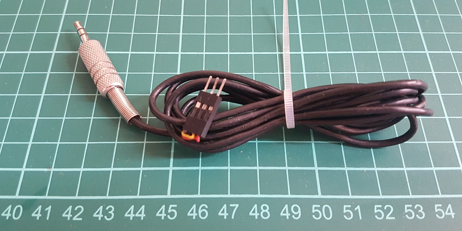 Yeah, it’s just a jack cable which I hook to my phone where I run the Function Generator Android App.
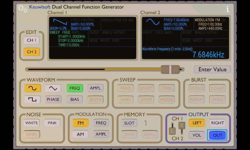
Sacrifice a pair of old headphones and you got yourself a dual channel function generator for free. Its sample rate is bad, the output level is horrible and there is no DC offset but you can’t beat this price point. This thing is just good enough to test audio stuff and it can be set up in no time.
The 10$ kit
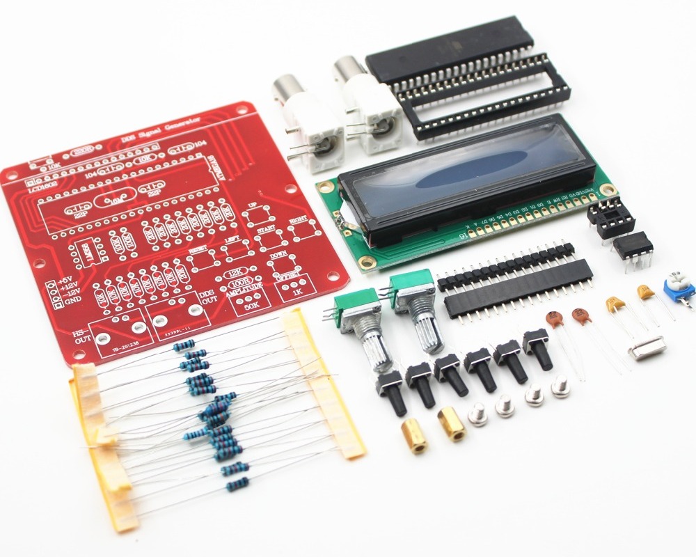
I got this mostly because I felt like building a kit and I imagine it would come in handy at some point. I like its design for its simplicity but I don’t enjoy using it because it’s awkward to operate. It didn’t come with a power supply so I adapted the picoPSU I’ve had around. The power supply was way more expensive than the kit!
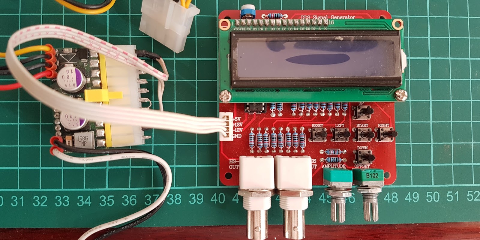
The design of this seems to be copied from ScienceProg.
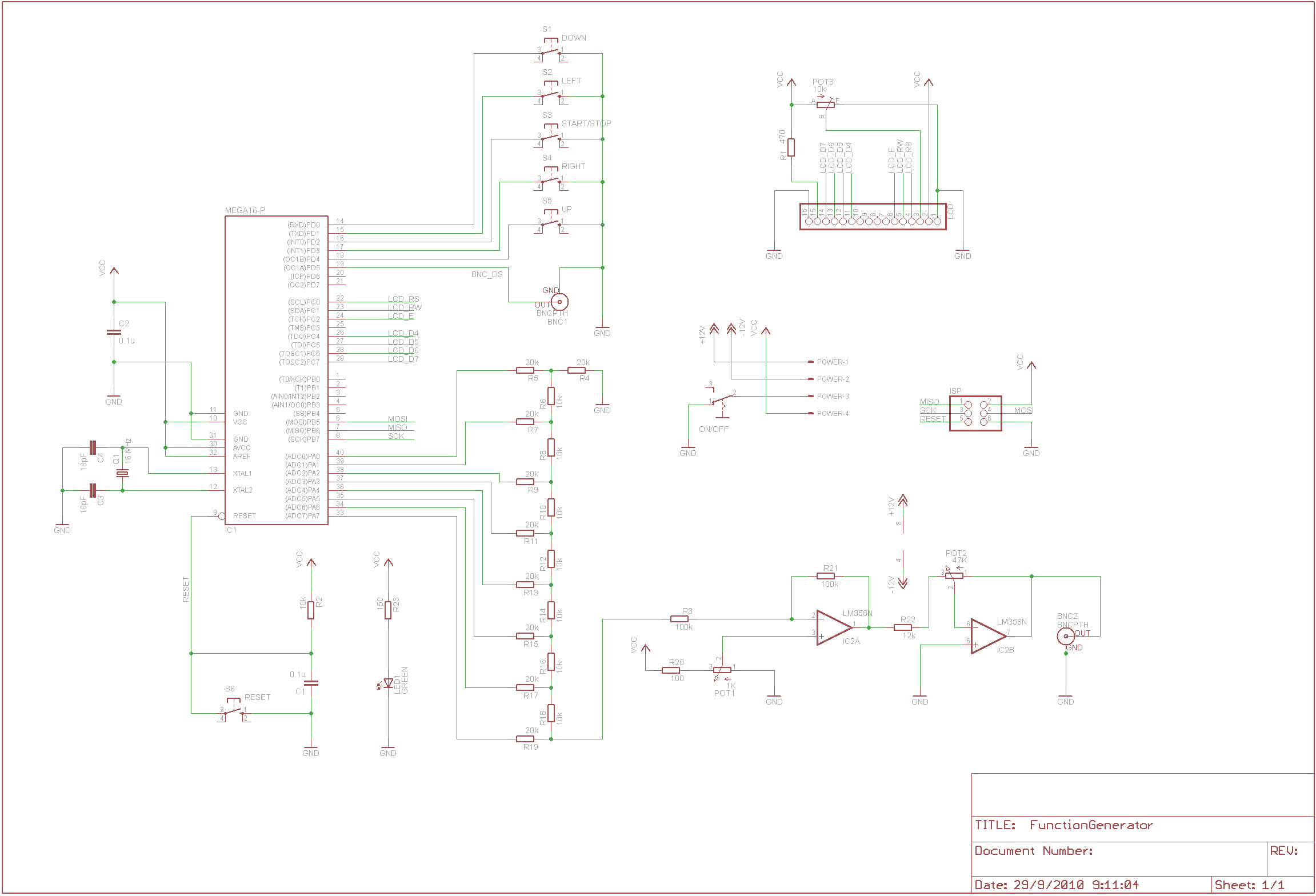
The Atmega16 micro generates signals which go in an 8bit R-2R DAC that then goes in an OpAmp for setting the amplitude and offset.
Its frequency range (0-65KHz) and output levels (10Vpp) are a few times better than the Android generator but I ended up using the Android generator way more than this. Without having it in a proper case with buttons it’s just not fun to use.
The 50$ unit
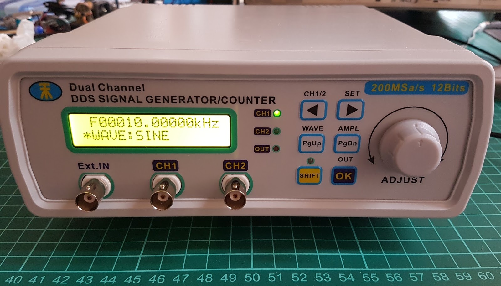
It comes fully assembled as a product, packed in a cardboard box, with charger and some cables for 50$ including shipping from China! Its specs are impressive to me:
- 0.01Hz-25MHz for sine and up to 6MHz for the other waves
- 5mVpp~20Vpp amplitude
- 12 bits amplitude resolution
- Arbitrary waveforms with memory for my own
- PC control over USB
- … and the list goes on and on
How is this possible?! What’s inside?
It’s actually got quite a few things which are not necessarily the cheapest if we got 1000 of them from a reliable supplier like DigiKey or Mouser.
From left to right:
- There is the switching power supply which converts 5V to +13V and to -13V. ~ 1$
- Next to the power supply it’s the ST 8bit, 16MHz microcontroller which most likely handles the LCD, menu and all that user interaction. < 1$
- Bellow the power supply it’s the USB-SERIAL converter which allows us to talk to the micro and an EEPROM for storing ARB waveforms and settings. < 0.3$
- Then it’s the Lattice MachX02 FPGA which is one of the cheaper ones but still one of the most expensive single chips from this board. < 6$
- The R-2R resistor ladder is a good way to make two DACs without spending money. When a 12bit DAC is implemented, 0.1% resistors should be used but here cost is the driving force so normal resistors were used. < 0.1$
- Then the signal flows in the two AD8017 variable gain amplifiers. < 6$
- Just before these but not in the signal path there are two LM OpAmps which control the DC Offset. These are super cheap. ~ 0.1$
- Last, under the way too small heatsink there are the most expensive chips. Those are the output buffers which actually drive the load that we hook up to our generator. My board had THS4022 which are pretty high-speed chips so at 25MHz the sine was still looking good. > 12$
Quicky adding these up, then making some very optimistic estimations for PCB, connectors, plastic case, LCD, power adaptor, cables, cardboard box and labor it probably goes to a minimum of 35$ for the cost of goods sold.
This also shows that both resellers and manufacturers operate on very thin profit margins. I am sure they pay less than my estimations and I would really learn how they do that.
Improvements I did
- Replace THS4022 with THS3092 which is slightly cheaper and can handle more current. This means we maintain the amplitude better at higher frequencies.
- Replace the heatsink with a much larger one. At high frequency or with low impedance loads this thing gets hot.
- Add some decoupling capacitors on the input of the power supply to remove some noise. On my board I added 1600uF and it was enough for medium loads.
- Add a small heatsink to the XL6007 switching converter. This works at the very limit of its output current when the generator is driven hard. In it’s SEPIC topology it should do 0.6A but the OpAmps want way more.
- Blocked the light from the LCD to bleed to the LEDs.
Improvements I wish the manufacturer did
- Much better SEPIC converter. This implementation can’t handle enough current.
- OpenSource software. I am sure nobody can make it cheaper so if the software was OpenSource people would be happy to improve it. For example, I don’t see why this unit wouldn’t support modulation.
- Better load handling.
- Lower noise.
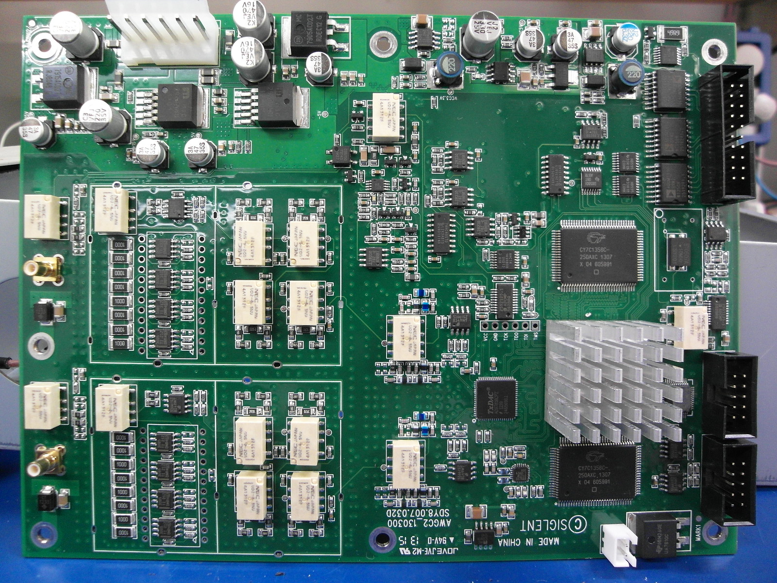
A professional generator board
Sigilent SDG 5000 series are entry level arbitrary waveform generators which might actually be used in a professional environment. This one is more than $500 and as you can see below, the main board is way more complex. The obvious things are a fancier FPGA, SRAM, a nice DAC and many OpAmps in parallel on the output.
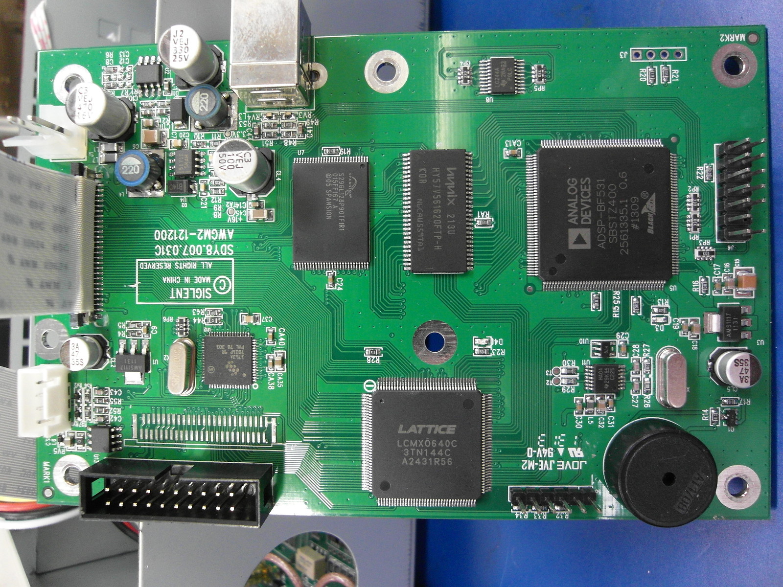
Another board does only the software and control stuff and this one is also quite impressive to me.
Conclusions
- Function generators can be fun :)
- As usual, you get what you pay for so don’t get the 10$ Kit.
- The 50$ MHS-5200A unit is good bang for the buck and with some small improvements and OpenSource firmware, it can be even better.