Pedal car electric conversion - preparation
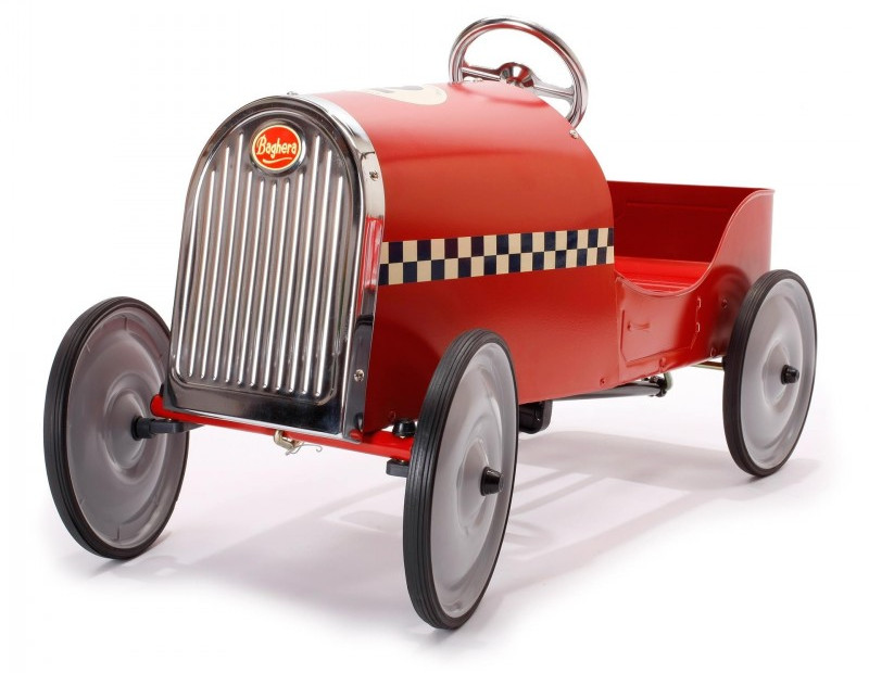
I did an impulse buy and got a Baghera Legend Red for my son and I decided to convert it from clean and boring pedal power to dirty and fun electric power. In this first part, I will do calculations and planning so I don’t order too many useless parts.
The motor
Of course, it all starts with the motor. It needs to be:
- cheap (it’s a pedal car conversion)
- fairly small and light
- powerful enough to move 20Kg
At ~24V there is a good selection of motors which would do it for this application. Electric scooter motors start at 250W so I guess I want something that handles 30-150W.
With motors I don’t think it’s proper to rate them only by voltage, current and power because you’re putting electricity through a wire/coil which creates a magnetic field that makes the motor turn. If the motor draws more current then it heats up and the wire insulation could be damaged. Usually, motors draw more current when they are loaded so I consider the rating loosely and I’d keep an eye on the temperature.
I have no problem getting a motor rated for 30W nominal and run it at 100W for a minute or so. It would only shorten the life of the motor slightly and it would provide the bursts of acceleration which are all the fun.
I got a good deal on this motor which is going to work just fine at 50-100W.
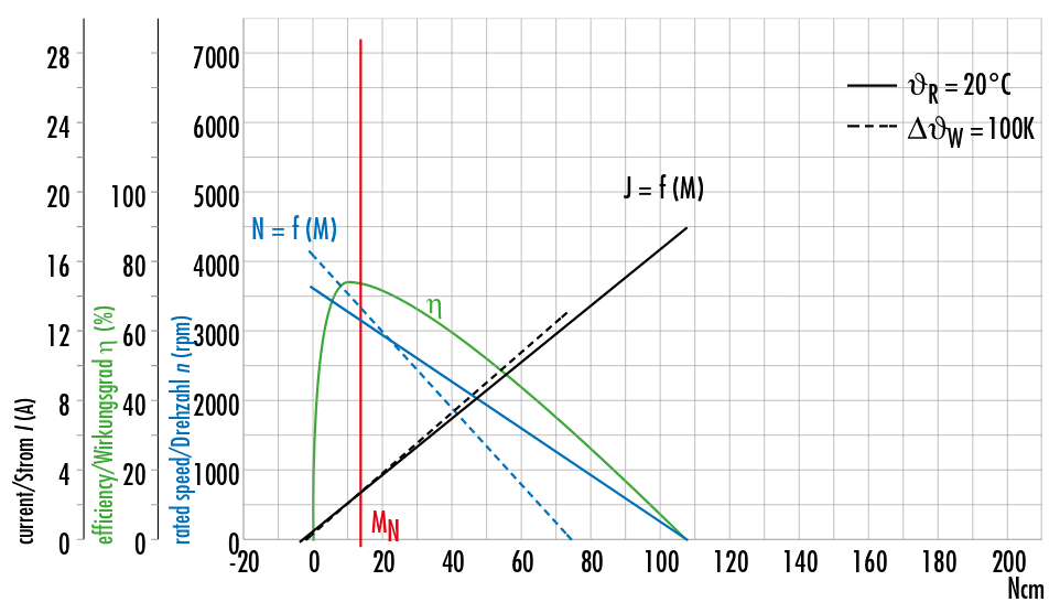 This one has a nice diagram showing the specs. Most of the cheaper ones don’t.
The battery pack
Once we have a general idea about our motor size we can think about the battery pack. We don’t really have real-life numbers with it but again, we make some assumptions.
The battery pack needs to satisfy 3 things:
- voltage ~24V. This will allow us to reach higher speeds but also to extract power from the motor.
- current handling >5A. To run our motor at 100W. We need this to accelerate faster or to go uphill.
- capacity >50Wh. To get a decent play time.
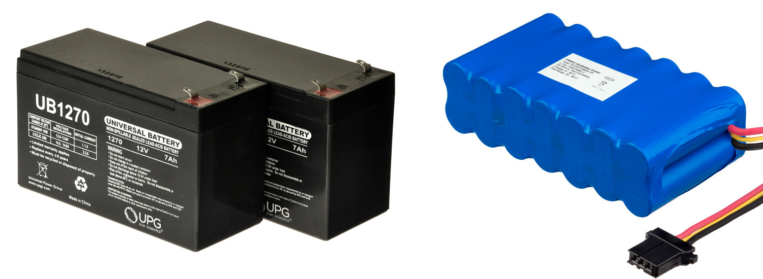
It could be as easy as 2x12V 7Ah UPS batteries. Both are less than 30$ new around here. The main disadvantage is that they weigh 4KG. Other than that these would be good because they have excellent current handling capability. One disadvantage though is that SLA batteries have this capacity if they are discharged at a very low rate, in 10-20 hours. If we discharge the SLA battery in 1 hour it’s capacity would be closer to 2/3 of what it says on the tin. Smaller capacity UPS batteries cost a little more because they’re not that common and weight just a little less.
Li-Ion has a better energy density (smaller & lighter) but the pack would be more expensive. One cell is 3.7V nominal so 24/3.7 => 6 batteries and a half. I’d go for 7 batteries in series because I want to have enough voltage even when the cells are discharged. When the batteries are fully charged the voltage is closer to 30V but that’s not bad for us. One cell is usually 2.2-3Ah and it’s not recommended to pull more than 4A of one of those cells. There are some high discharge cells on the market but those are more expensive. We can improve both current handling and capacity by adding more batteries in parallel. It looks like the pack that we need is 7S2P (7 series 2 parallel). This would provide a similar runtime for 1/4 of the weight and 2x the cost.
The speed controller
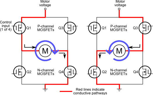
To control the speed of the motor we need to control the voltage that gets to it. Usually, this is done with PWM (pulse width modulation) on a MOSFET. Something similar was done for a flashlight in the past.
To control direction and braking, we need 4 of those MOSFETs in an H-bridge configuration. Also, those MOSFETs are coupled with a flyback diode to dissipate the inductive energy that is characteristic to motors.
The cheaper speed controllers are just 10$ so I’m going to buy one because this project is not about the speed controller. Knowing how it works should help in case it breaks.
The drivetrain
To transfer power from the motor to the wheels, I think there are 3 practical options:
- gears (hard to mount)
- chain drive (more efficient)
- belt drive (less noisy and doesn’t require lubrication)
I am choosing belt drive because I care about noise and not having to grease it.
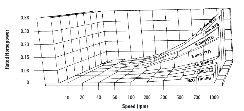
There is a large variety for belt drive and I am going for timing pulleys of the HTD3M variety because they are fairly common, with decent performance and not expensive.
 When transferring power from the motor we need to reduce the RPM and increase the torque. The driving pulley is the smaller one and the math is like this:
 If the driving pulley has 15T (T = teeth) and the driven one has 120T then RPM is decreased 8 times. Our motor is rated for 3300 RPM so, at the axle we’d have 3300/8 ~ 412RPM. Because the diameter of our wheels is 10” then the theoretical top speed is 20KM/h. That’s very nasty for a pedal car which will be driven by a toddler.
After doing a little bit more reading, it seems that because of the higher RPM I can’t really use a 15T pulley, I have to use a 20T one. This means lower torque and high speed up to 26KM/h. I see these options:
- limit top speed electronically (torque stays the same but it’s simpler for me)
- add another set of pulleys (gain more torque with lower top speed)
Browsing pages 67 to the end in this document indicate that given our 108 Ncm peak torque a 6mm belt wouldn’t do it and a 15mm one would be more than enough. We are using a very short belt so our length correction factor is ~0.7 and to account for beginner errors I am just going to go for the beefier option.
Once we have our choice of pulleys we need to calculate the belt length. Since the math is a bit more involved for that I provide a calculator below which does the heavy lifting.
In my case, 405mm is close enough to a standard belt size but I’m getting a 408mm belt to make sure it can be mounted.
Servo steering
I am thinking to implement remote control so I need to be able to steer the car. I am just going to do it like they do it on RC cars, with a servo motor.
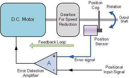
Basically a servo motor it’s special because it can rotate or push to a specific angle or distance and then keep that position steady. To do that it has a positive feedback loop which compares the input signal which specifies the position, with the actual position and tries to keep them in sync.
Generally, servos are controlled with PWM at 50Hz and rotate 180 degrees.
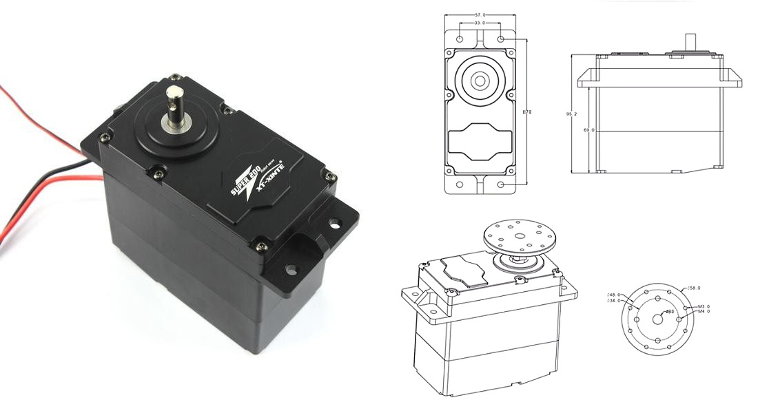
They tend to have high torque because they have a gear reduction mechanism but I’m getting one which is way bigger than the ones used for RC cars because the car is much bigger. I’ll use a SUPER200 servo which is rated for 200Kg/cm which means it can lift 200Kg at 1cm distance from the shaft. If the lever which moves the wheels is mounted 20cm away from the shaft I still get 10Kg of force to move the wheels so that’s good.
Quick CAD modeling
I believe I have pretty good imagination and I can see in my mind how things fit together. That was a problem in the past because there are always differences from reality so I decided to do a little bit of modeling to confirm all would fit together.
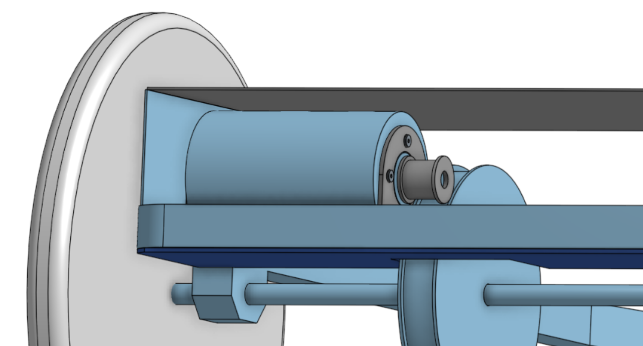
Errors were visible right away so look at the image below.
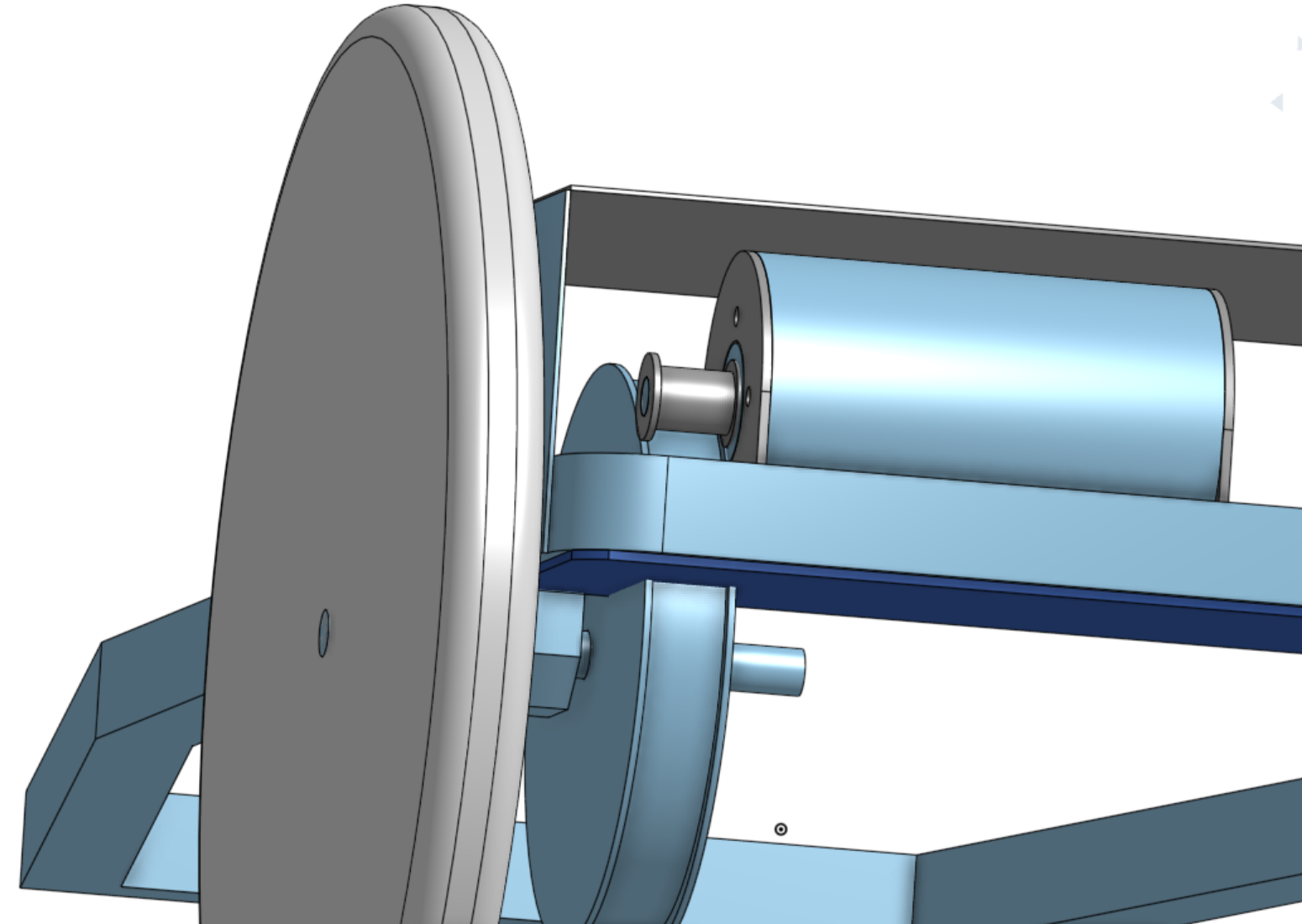
- The large timing pulley cuts in the dark blue metal plate which supports the motor near one of the edges which supports it. I will try to mount the motor 180 degrees rotated so the metal plate would have better structural integrity.
- The two timing pulleys collide. I would have to make the metal brackets which support the motor narrower so I can place the motor 10mm closer to the back edge.
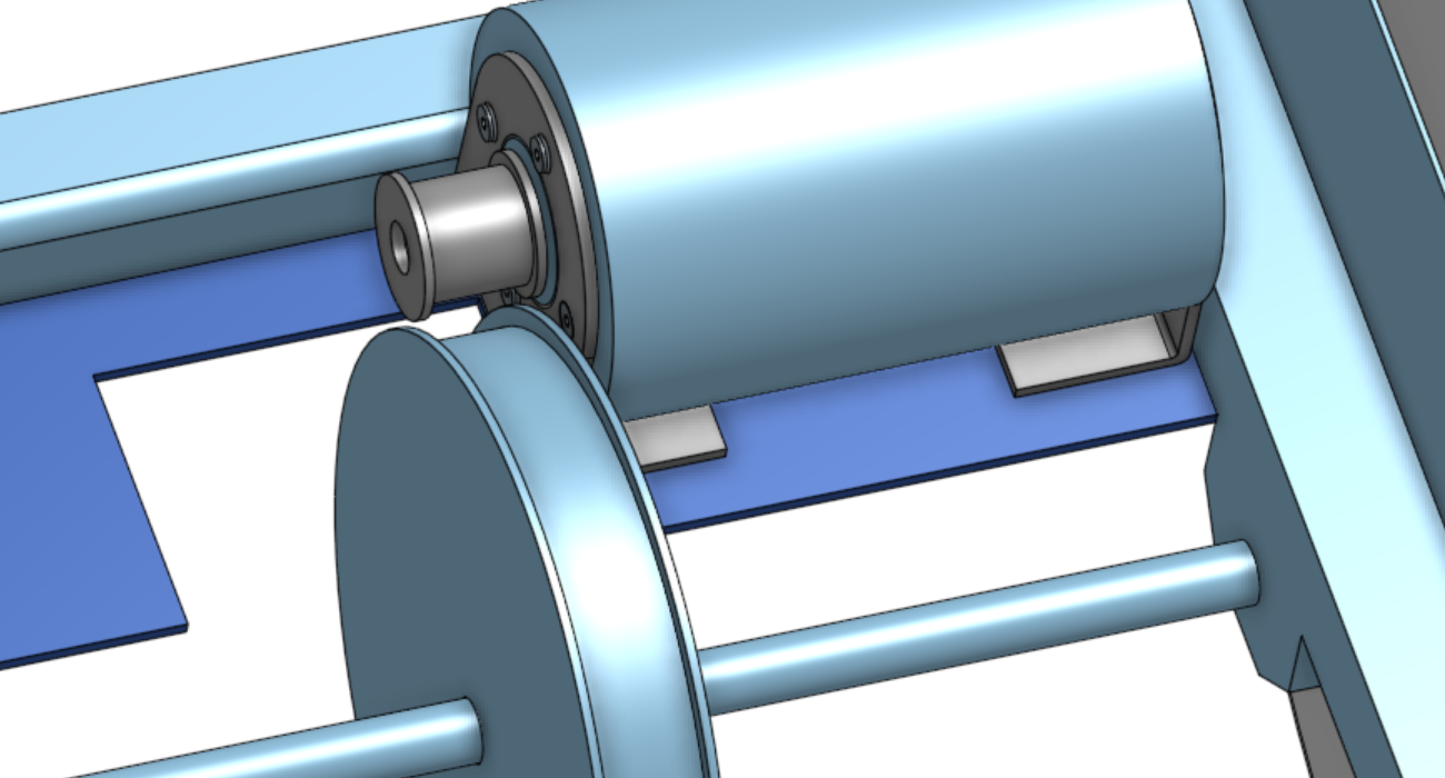
- The small timing pulley rubs on the motor. I will mount it 2mm offset on the shaft and hope one of the sides will not fall off. I don’t want to use a thinner pulley because we determined earlier 15mm would do it.
After putting a bit more thought into it, this assembly makes more sense like this:
To view the actual 3D assembly click HERE.
BOM for this conversion
- pedal car
- GR 63X25 DC motor
- 24V battery pack
- motor speed controller
- 10A fuse
- acceleration pedal
- threaded rod as a drive train
- 20T & 120T HTD3M timing pulleys
- 408mm timing belt (15mm wide)
- SUPER200 servo
We’re getting close to 300$ in parts, without considering the cost of the car.
… I’ll think about it.