Testing charge-pump ICs
Sometimes we need a negative voltage rail. There are several ways to obtain that but most likely the easiest is to use a charge-pump IC with only two capacitors. Because the datasheet doesn’t always paint a clear picture I decided to order a few and do my own testing for the things I care about (current, ripple, switching frequency).
Application
I suppose that you already have an application in mind since you are reading this. Nevertheless, this time my use case is powering up OpAmps which I will use in an audio application. Is might not work well for this but that’s what I want to find out.
Charge pumps are essentially integrated in almost all flash-memory and they are instrumental in deleting data. As standalone devices they are not common place.
Possible issues
Let’s see quickly how they work. In the image below we can see that we essentially have 4 switches.
Closing S1 and S3 charges C1 in the first half cycle. In the second half, S1 and S3 open and S2 and S4 close. C1 is then in parallel with the reservoir capacitor C2. If the voltage across C2 is smaller than that across C1, charge flows from C1 to C2 until the voltage equalizes. Since the polarity is inverted then the voltage would be negative.
The more current you draw from C2 the more ripple you’ll observe. The frequency of the ripple will be the frequency at which the switches operate.
For powering OpAmps this is clearly not ideal because charge pumps are switching devices which, of course, have ripple on the output. On the other hand, OpAmps have a PSRR (power supply rejection ratio) which define how much of the noise from the power supply will end up in the output of the OpAmp.
In the image below we have a generic graph for PSRR.
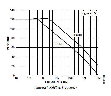
This essentially tells us that at 10kHz the rejection of noise from the negative supply is ~ 105 dB. This means that if you have 10 kHz ripple on the negative supply, the noise would be 0.000005 of the audio signal. Even if we amplify the signal 10x it’s still going to be great. Nevertheless, this is OP4177 which has a great PSRR. For many other OpAmps we don’t even have this data in the datasheet so we just need to do some tests and see for ourselves.
It looks great. Even with 100x worse PSRR it should still be good enough.
Also, I have another plan. If we can use the charge pump at greater than audible frequencies then we could probably even ignore this data. A young and super pretentious teenager should be able to hear all the way up to 20kHz. Once you get older you don’t hear high frequencies well anymore. Because I was never a golden ear I will count on measurements.
In short:
- Large ripple + bad PSRR => noisy output.
- Small ripple at high frequency + decent PSRR => happiness
Change pump ICs
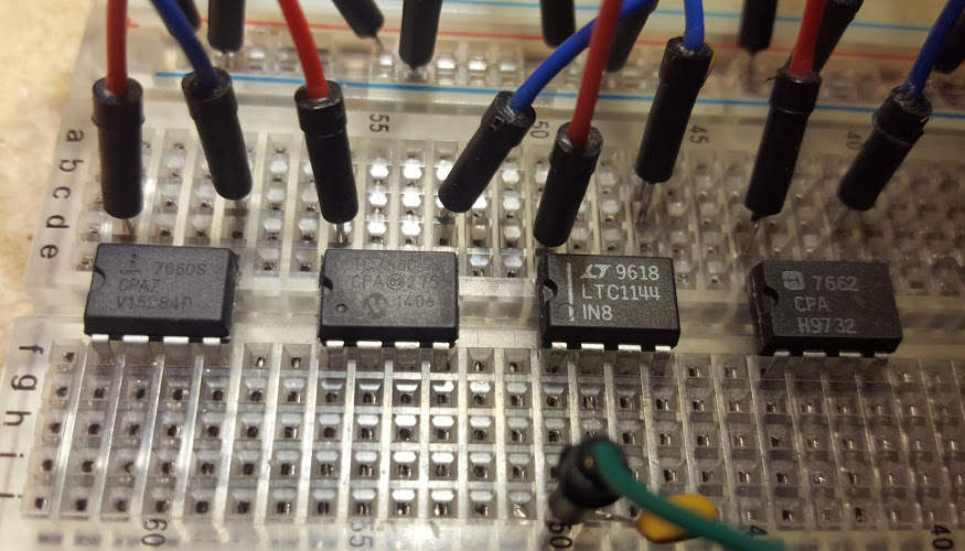
| Intersil 7660S | Microcip TC7660 | Linear LTC1144 | Misterion 7662 |
I am interested in testing the following:
- maximum current they can dump in a 100 Ohm resistor when supplied with 8V
- ripple while loaded with the 100 Ohm resistor
- operating frequency
Some of these have a boost functionality that can increase the operating frequency so I will also test this where available.
| Intersil 7660S | Microcip TC7660 | Linear LTC1144 | Misterion 7662 |
|---|---|---|---|
| 37mA | 41mA | 36mA | 31mA |
| 1.6V | 1.0V | 1.3V | 1.5V |
| 3kHz | 6kHz | 3kHz | 2kHz |
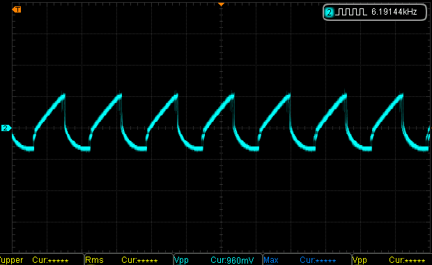
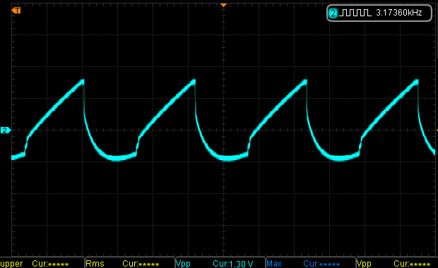
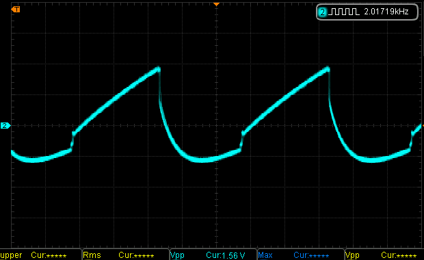
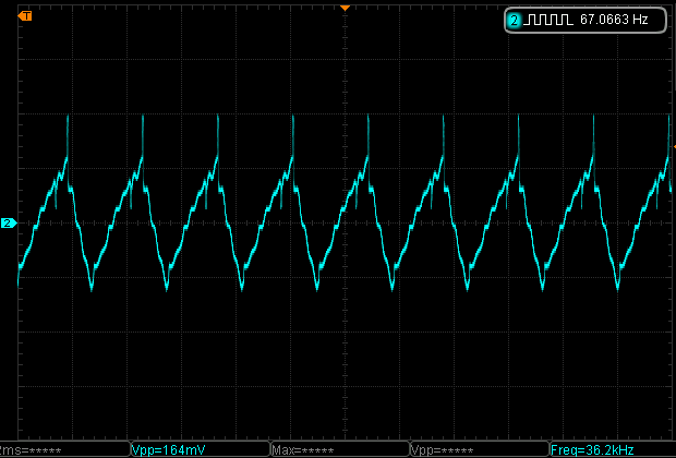
We have some pretty picture too, taken with the scope. You can say which is which by looking at the Vpp and frequency values.
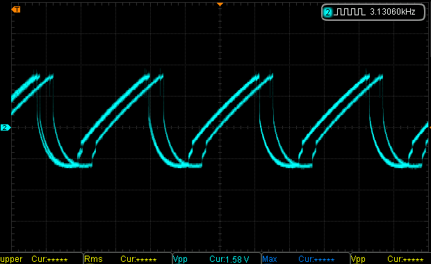
The doubled waveform is obviously a trigger error captured by the scope.
Out of the bunch, the last two also had a boost function which would increase the switching frequency. That should have also been available for Intersil 7660S but it didn’t work. Perhaps I had a fake of defective batch.
| Linear LTC1144 + boost | Misterion 7662 + boost |
|---|---|
| 30mA | 30mA |
| 0.7V | 1.2V |
| 37kHz | 2.7kHz |
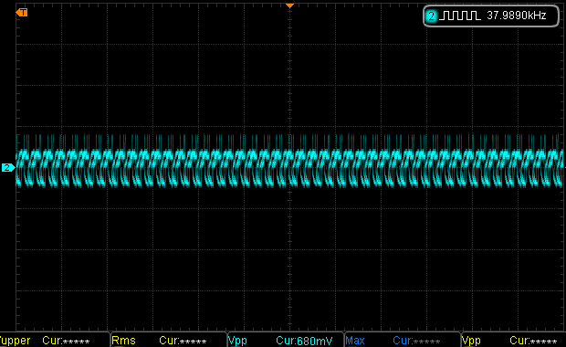
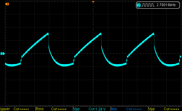
LTC1144 actually stats to look acceptable, especially compared with the others. It’s oscillating at much more higher frequencies than audible. Even though the ripple is huge, at least is much better than the others. I guess it makes sense now that is twice the cost of the next one in the bunch.
Still, 700mV ripple is huge. According to the datasheet we should be able to do much better.
At the bottom of page 7, the datasheet tells us that capacitors are not critical. On the other hand they also show that most of the charts go up to 20mA, even though one goes up to 50mA. Still, regular 10uF electrolytic caps have a pretty big ESR. At high frequencies, the resistance of the caps should greatly influence the transfer of energy from C1 to C2, thus it will increase the ripple and decrease the output current.
Let’s test LTC1144 with 10uF capacitors that have much lower ESR.
| Tantalun | Ceramic | |
| Current | 40mA | 39mA |
| Ripple | 0.8V | 1.0V |
| Freq | 3kHz | 3kHz |
Already a big difference even at the lower frequencies. Surely it would be better once we activate the boost function.
| Tantalun | Ceramic | |
| Current | 30mA | 33mA |
| Ripple | 0.3V | 0.16V |
| Freq | 37kHz | 36kHz |
That’s more like it! LTC1144 is the only decent charge pump for this job. With 10uF ceramic caps, it shows the best performance, even though that is not mentioned in the datasheet. Perhaps I am missing something but even so, tantalum caps are a much better option and they make a huge difference.
Conclusions:
- The difference between pin compatible parts ca be huge.
- The ESR of capacitors can be a huge influence in various applications.
- Charge pumps could be a very decent option where low power is required.
- LTC1144 is significantly more expensive than the bunch that was tested but it’s performance is much better.
One thing that was brought to my attention is that I didn’t mention the voltage drop is huge with our 100 Ohm load. After we account for the output resistance in our IC, if we put 8V in, we will get -3.3V out.
Unfortunately I think I need a few times more current than these can deliver for driving headphones decently. Even though I could parallel more charge pumps ICs, I will also consider LT1054. If that doesn’t work perhaps I will have to consider a switching power supply with an inductor.