IoT Fuzzy Clock
Let’s see how to make a very precise clock that will be read with a large margin of error. It should be easy for the technically inclined and it can also be fun.
The purpose is to introduce some very versatile and yet cheap building blocks in the most straightforward way possible. It was written for beginners and it explains a bunch of things from scratch.
Above you can see the green LED is the minute, the red one is the hour and the blue one indicates atmospheric pressure. It’s a 12 hour clock and in the time lapse it goes from ~ 5:10 to 6:50 PM. When the blue LED is close to the left there is a small chance of rain and when it’s close to the right there is a significant chance of rain.
BOM (Bill of materials)
- ESP8266 module
- WS8211 LED strip
- Any USB charger
At the time of the writing both the module and the LED strip could be purchased for under $10 online. I would never recommend getting a cheap USB charger because it could burn down your house or create a lot of RF noise that could interfere with other stuff such as the WiFi signal.
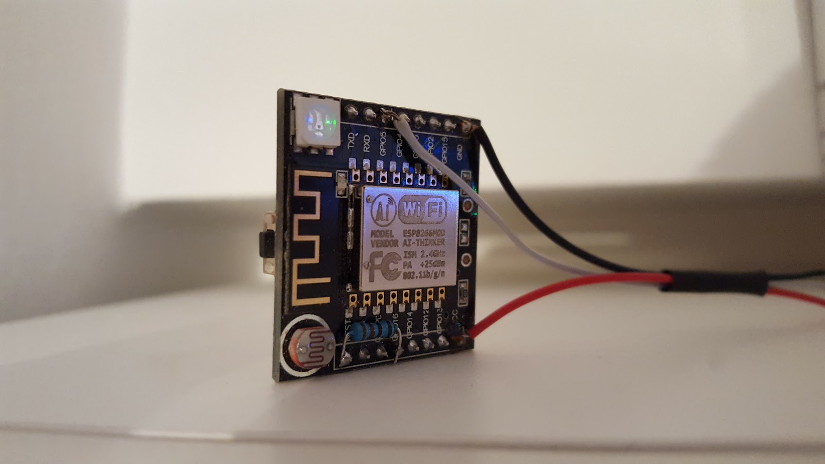
ESP8266
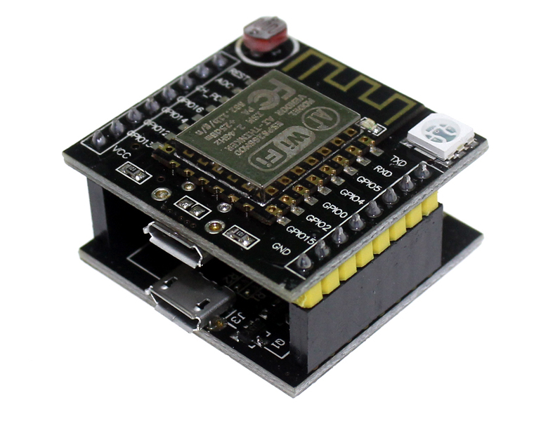
ESP8266 is a very cost effective chip that integrates WiFi with a capable microcontroller. We will be using a module that uses that chip along with flash so we could store our code and a voltage regulator so we can power it from 5V.
I used the Witty board because I already had it lying around and because for this particular project it comes with an LDR soldered on. I will use the LDR to detect the ambient light and control the intensity of the LEDs accordingly. You can get the module from Aliexpress if you don’t have a faster alternative.
Features
- 32-bit RISC CPU running at 80 MHz
- 64 KiB of instruction RAM, 96 KiB of data RAM
- External SPI flash - usually 4 MiB
- IEEE 802.11 b/g/n Wi-Fi
- UART on dedicated pins
- 16 GPIO pins
- one 10-bit ADC
- SPI, I²C
To see the beautiful piece of silicon check out the work done by Zeptobars.
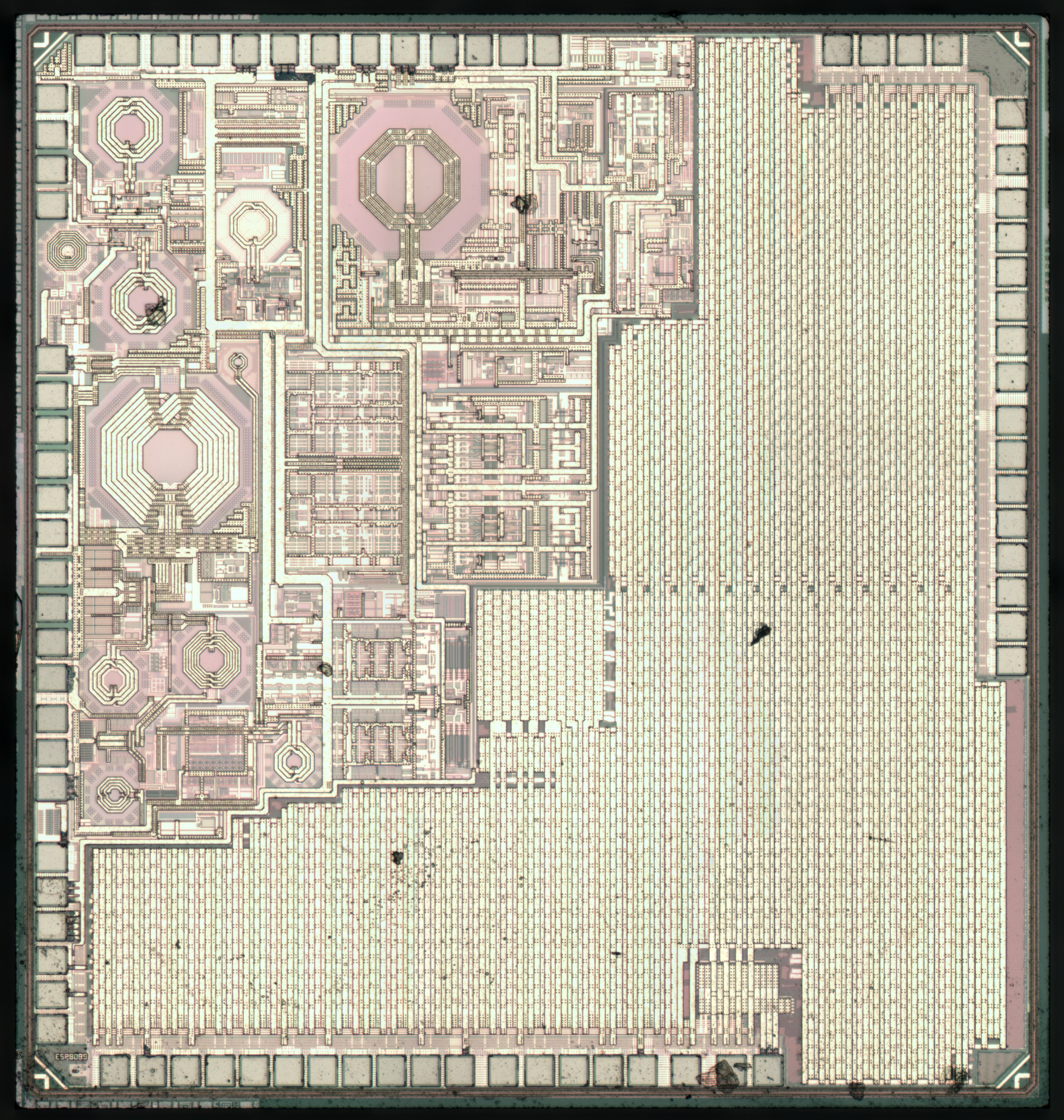
WS2812B
We are going to use an RGB LED strip with individually addressable LEDs. Different LED colors will indicate different things and the position on the strip will indicate a relative value.
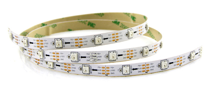
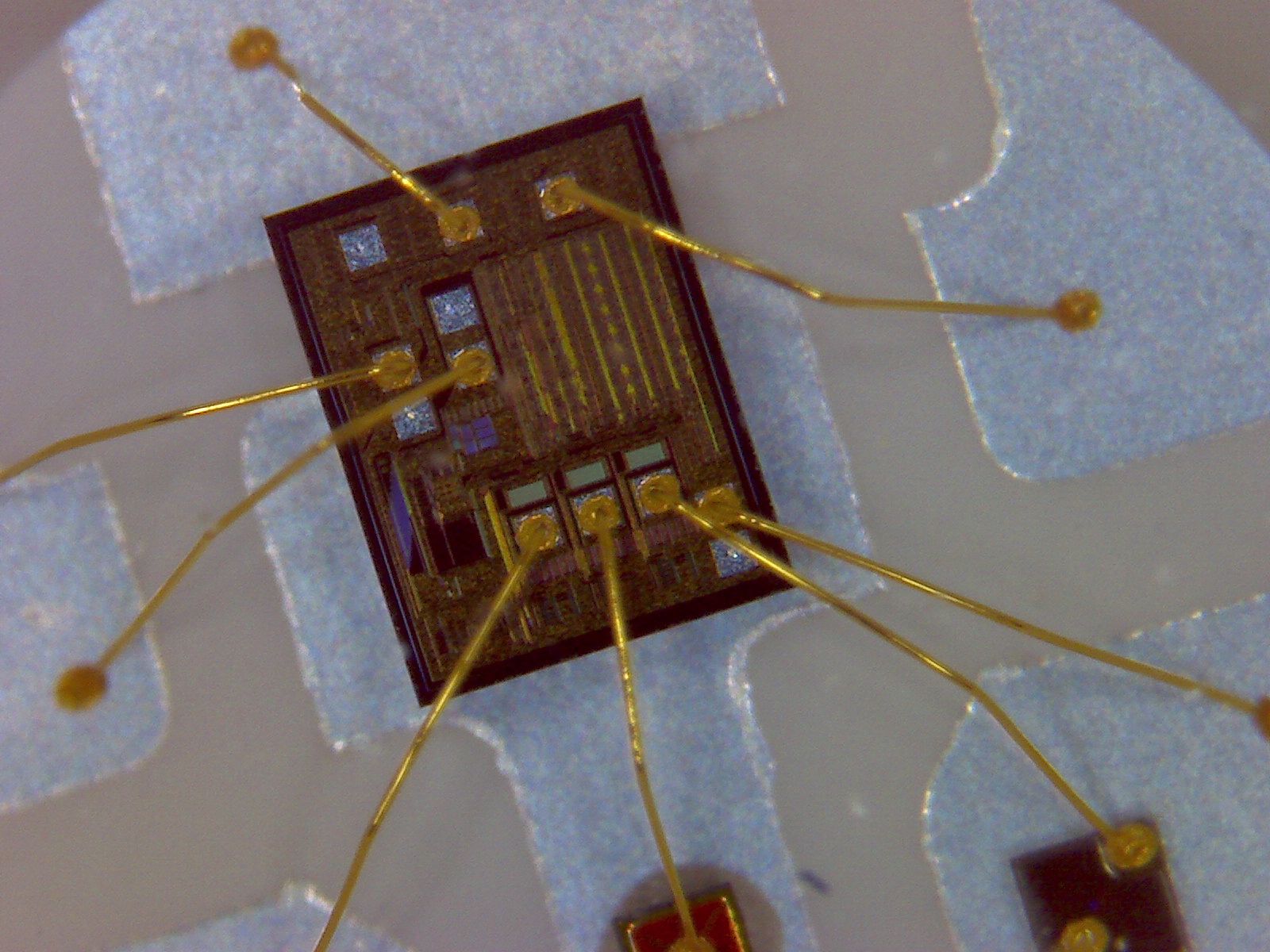
WS2812 is essentially a capsule which has red, green and blue LEDs connected directly to a chip. This makes it possible to digitally control 256 brightness levels for each color to obtain 16M colors. Depending on the version of the chip we could change colors 400-800 times per second. These can be cascaded and the signal would be sent through a one wire interface. In theory we could achieve 30fps with 1024 of these huge pixels. These work great at 5V, have reverse polarity protection and are very cost effective.
For this project I plan to use only one color at a time and to change it every minute so we will be well under spec. For this application 60 LEDs would make the math easier because it divides nicely with 60 minutes or 12 hours. Nevertheless I only have 30 LEDs at hand so I am going to use that because we are making the fuzzy clock :)
Soldering
Soldering is easy. Connect the red wire (+5V) to VCC, the white wire to GND and the green wire (data in) to GPIO5. The signal travels in the direction of the arrow on the LED strip so just keep that in mind.
Also add a small resistor (less than 1K) between GPIO16 and REST. This will bring the micro back to life then it’s done sleeping.
Software
ESP8266 works with quite a few different SDKs so it can be programmed using different languages. MicroPython is very nice if you like Python, NodeMCU for Lua, Arduino for C++ and there is even a firmware for BASIC. I played with all these and personally I prefer Arduino because it has libraries for almost everything. I also read the documentation for mongoose-iot but as of 2016 it’s just getting started. It also looks interesting but time will tell if it’s going to be an enterprise product or for everybody.
Arduino
Yeah, you all heard about this one. They are some people that like to fight who make some boards and an IDE.
I like the boards that inspired a lot of people and because they were OpenSource it also became possible to get clones for much smaller prices. This inspired even more people. Hardware wise, I am not impressed with the boards. After all these years, I think they are still lacking in some areas.
Now the IDE is a very different story. I think the IDE got better and better. There are many easy to use libraries out of the box. You can find a bunch of other libraries on the Internet. You can even use all these ecosystem for unofficially supported boards and that’s exactly what are we going to do.
The IDE is written in Java so make sure you have JRE. It uses a library from the Wiring project to make it easy to interact with the pins of the microcontroller. It organizes the code in a minimum of two functions setup() and loop() which are pretty self explanatory. setup() runs only once when the microcontroller is powered up and then loop() runs continuously. The Blink sketch makes everything clear.
Just remember that the Arduino IDE is not only for Arduino boards.
Installing with Boards Manager is usually the easiest to get started with ESP8266.
Code
The big picture is:
- We import libraries
- ESP8266WiFi makes it easy to connect to WiFi and go to sleep
- NTPtimeESP is an extension that gets us nicely formatted time
- Adafruit_NeoPixel makes it easy to work with WS2812B LEDs
- ArduinoJson helps us handle the JSON data that we get from an external API
- We define a bunch of constants and variables
- We only execute the
setup()function because we want to run things only once and then go to sleep for a little while. When we come back from sleep we reset the micro and thesetup()function is executed again. This way, most of the time the microcontroller is actually powered down so it’s drawing very little energy. - Some functions are defined to make it a bit more readable
- WUAPI connects to api.wunderground.com to get the barometric pressure for our city
- showWeather formats the JSON weather data
- getShowData retrieves data from NTP, calculates the position of the LEDs and lights them up. Yeah, this one is not very well structured but it is late and I want to finish this post.
Possible improvements
- OTA (Over The Air) software upgrades
- Add a buzzer and make a short sound every hour during the day
- Add a visual or acoustic alarm that could be dismissed with a press of a button
- Add a PIR sensor and trigger an alarm when a person’s presence is detected
- Connect a HTU21D or a SHT10 temperature and humidity sensor and put the data in the cloud
- Make it flash crazy beautiful colors for various anniversaries
- Make it possible to adjust the timezone by pressing a button.
- If it can’t connect to WiFi, go in STA mode so the user could connect to it and do to a web interface from where he could setup WiFi.
Conclusion:
I guess you could say this is a IoT project but let’s not say that because it doesn’t sound very nice. :)
We are doing it this way because it’s much simpler than if we used an RTC. We don’t need to adjust the time. We don’t need to maintain power to maintain the time. We get daylight saving adjustments automatically.